
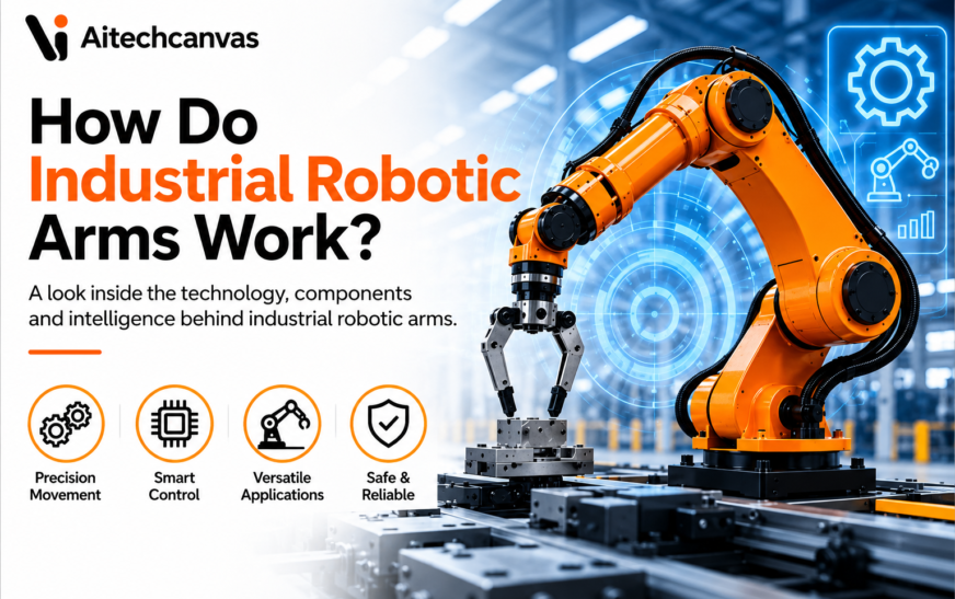
How Do Industrial Robotic Arms Work? Industrial robotic arms work by combining servo motors, precision gearboxes, sensors, encoders, and a real-time controller to move each joint with exceptional accuracy. The controller continuously compares the arm’s actual position with its programmed target using closed-loop feedback, making tiny corrections in milliseconds. This enables robotic arms to perform precise, repeatable tasks such as welding, assembly, painting and material handling with sub-millimeter accuracy.
Walk into any modern automotive body shop and you will see the Technology that has transformed global manufacturing. Industrial robotic arms weld, assemble, and move components with remarkable speed and precision, often completing thousands of high-stress motions during a single shift without losing alignment. According to the International Federation of Robotics (IFR) World Robotics 2025 report, factories installed 542,076 industrial robots in 2024, increasing the global operational fleet to approximately 4.66 million units, a 9% year-over-year growth..
What Is an Industrial Robotic Arm?
An industrial robotic arm is a programmable manipulator built to carry out physical tasks on a production floor. It as an automatically controlled, reprogrammable, multipurpose manipulator that moves along three or more axes. That word multipurpose is what separates these machines from single-function equipment.
It is a completely different class of hardware from a hobby or desktop unit. It relies on cast steel or aluminum members, high-torque drives, sealed enclosures, and joint housings rated to survive coolant mist, weld spatter, and years of vibration. Its core purpose is to automate work that is dangerous, monotonous, or physically punishing.
The defining trait of these machines is repeatability. A well-maintained six-axis arm returns to a taught coordinate within a fraction of a hair’s width across a service life that commonly runs 80,000 hours or more before a major overhaul. Most units move across six rotary joints, called axes. This gives the tool enough freedom to reach around parts that fixed machinery simply cannot handle.
The Core Components That Make an Industrial Robotic Arm Work
How Do Industrial Robotic Arms Work? The answer begins with understanding the core mechanical and electronic components that work together to deliver precise motion. An industrial arm is a stack of structural, mechanical, and electronic subsystems that stay in sync to the microsecond. Each component explains exactly where accuracy is won and lost. Robot arm anatomy includes the base, shoulder, elbow, wrist, joints, links, and end effector that work together to produce precise industrial motion.
Base and Structural Frame
The base is the heavy mass everything else pushes against. It bolts the arm securely to a floor, gantry, or seventh-axis track, absorbing the massive reaction forces created every time the arm accelerates or stops hard. Cast iron and aluminum structural members extend from it, routing internal wiring, air lines, and gearboxes directly through the body.
Rigidity here is critical rather than cosmetic. A few thousandths of a millimeter of flex in the casting shows up magnified at the tool tip because the arm acts as a lever and the error grows with reach.
Joints and Links
The moving skeleton consists of a set of rigid links connected by powered pivot points called joints. Each joint delivers one rotary axis, running on crossed-roller or precision ball bearings. These bearings carry heavy radial and moment loads at low friction so the arm moves smoothly even under a full payload.Modern robot arm joint design minimizes backlash while maximizing strength, precision, and long-term durability.
Servo Motors and Drive Systems
Electrical energy becomes controlled by physical motion through AC servo motors mounted at each joint. They are built for low rotor inertia, fast dynamic response, and continuous duty so the controller always knows the exact rotor position.
Robot Controller
The controller acts as the core brain housed in the cabinet beside the cell. It runs a real-time operating system that solves complex motion algorithms thousands of times per second. Current-generation examples include the FANUC R-30iB Plus, ABB OmniCore, KUKA KR C5, and Yaskawa YRC1000, each pairing motion computation
Sensors and Feedback Devices
Optical or magnetic encoders sit on each motor shaft to tens of thousands of counts per revolution. Absolute encoders, now standard across the industry so the bio mechanical robots no longer needs re-homing procedures each morning.
End Effectors
The tool mounted at the wrist flange is the end effector, also known as end-of-arm tooling (EOAT). It is the specific part that touches the product, turning one generic arm into a welder, packer, or machinist. The primary categories include:
- Two-finger and three-finger mechanical grippers for positive part holding
- Vacuum cup arrays for sheet metal, glass, and flat cartons
- Resistance spot-welding guns and continuous arc-welding torches
- Electrostatic paint atomizers for even, low-waste coating
- Powered spindles carrying cutting or deburring tools
- Magnetic and custom fixtures for fast steel transfer
How an Industrial Robotic Arm Executes a Task
Executing a single automated task involves a fast, ordered sequence into controlled physical motion and back into a status signal.
1. Program Loading and Interpretation
The primary cell controller signals the arm to run a specific job file. The robot loads that program’s motion profile, path speeds, and I/O logic into active memory and stands ready to execute.
2. Kinematic Calculation
Before anything moves physically, the controller solves inverse kinematics. This converts a target tool position in 3D space into the exact joint angles needed to reach it. On a six-axis arm, more than one mathematical solution can reach the same point.
3. Power Distribution to Servo Drives
The controller sends low-voltage commands directly to the servo amplifiers. Those amplifiers deliver precisely shaped three-phase electrical current to the joint motors, producing controlled torque at each axis.
4. Coordinated Joint Rotation
Every motor turns its designated axis at a calculated speed. The reducers multiply that rotational motion, and the links swing smoothly along a planned .
5. Continuous Sensor Feedback
As the joints move, the encoders report shaft position back to the controller thousands of times per second. This ensures the machine always knows its true physical position versus where it should be.
6. Real-Time Path Adjustment
When payload weight, friction, or mechanical resistance nudges the arm off its planned path, the servo loop catches the deviation within a single control cycle. It trims motor current immediately to pull the trajectory back on line.
7. End Effector Activation
The instant the wrist reaches the target coordinate, the controller fires the tool. A pneumatic valve actuates, a gripper closes, or a weld arc strikes to complete the physical work.
8. System Status Reporting
With the action complete, the arm updates its internal status register and signals the cell controller that the cycle is finished, clearing the line for the next part.
How Robot Motion Is Controlled with Multiple Axes
To understand how do industrial robotic arms work, it is essential to understand how multiple axes coordinate movement with high precision. To understand how an arm moves through space, start with degrees of freedom. Each independent axis adds one degree of freedom, and that total count determines how flexibly the tool can be positioned and oriented in space.
The workhorse of modern industry is the six-axis articulated robot. Six axes represent the minimum needed to place a tool at any position and orientation inside the work envelope:
- 1st is at the base rotates the whole body left and right
- 2nd is at the shoulder tilts the lower arm forward and back
- 3rd is at the elbow raises and lowers the upper arm
- 4th rotates the upper arm along its length
- 5th pitches the wrist up and down
- 6th spins the tool flange continuously
That creates the distinction between linear moves, where the tool travels a straight path, and joint moves, where the fastest route arcs the links through open space. Path planners blend the two, ramping acceleration smoothly to avoid the jerk that damages gearboxes over time. Six axes is the most common setup, but not the only one. SCARA arms use four axes for flat-plane assembly, delta robots use three or four for high-speed picking, and seven-axis arms add an extra degree of freedom to reach around physical obstacles.
How Industrial Robots Maintain High Accuracy During Operation
Precision at high speeds is engineered into the system. It starts with closed-loop control from the joint encoders, which read a finely etched glass disk with light sensors to resolve shaft rotation to tens of thousands of counts per turn.
Manufacturers close this gap through software calibration. Options like ABB’s Absolute Accuracy model each individual arm’s true physical geometry. At the same time, temperature sensors in the joint housings let the controller compensate mathematically as the structure warms up over a shift. This matters most in offline-programmed work where the path comes straight from CAD software and the robot must hit coordinates it was never manually taught.
The Role of Sensors, Vision Systems, and Real-Time Feedback
How Do Industrial Robotic Arms Work? Sensors, machine vision, and closed-loop feedback ensure every movement remains accurate even when conditions change. Older production lines depended heavily on rigid fixturing where parts had to sit in exact nests. Modern manipulators use vision and force sensing to adapt to parts as they arrive, cutting tooling costs and allowing much messier feeding systems.
Even without a dedicated external sensor, the servo drives provide an active safety layer. If the arm strikes an unmapped obstruction, motor current spikes immediately. The controller cuts drive power and engages mechanical brakes within milliseconds.
How Industrial Robotic Arms Communicate with Other Factory Equipment
An industrial arm never operates in isolation. It runs on high-speed industrial networks that keep every physical motion in step with the machinery surrounding it.
At the plant level, a Manufacturing Execution System (MES) tracks total output, part serial numbers, and machine health metrics. The arm logs completed cycles, cycle duration, and drive diagnostics up to that system increasingly over OPC UA feeding predictive-maintenance models that flag a failing reducer weeks before it seizes.
Common Manufacturing Tasks Performed by Industrial Robotic Arms
Because the exact same mechanical platform changes jobs with a new tool and program, one arm covers wildly different work. The IFR reports that the automotive sector remained the single strongest driver of robot demand in 2024, with welding and material handling leading the way.
Spot Welding
Automotive body lines lean heavily on large arms carrying high-current resistance spot-welding guns. The robot swings the gun around a stamped panel, clamps down with thousands of pounds of force, and passes localized electrical current to fuse the steel sheets in under a second per weld.
Arc Welding
Gas Metal Arc Welding rewards smooth, continuous path control. The controller drives the wire-feed torch along a precise route, adjusting angle and travel speed to lay an even bead without burn-through. Seam-tracking sensors let the arm follow real joints on parts that never sit exactly where the software program expects.
Pick-and-Place
High-speed delta and six-axis arms equipped with light vacuum tooling move products between lines at a blistering pace. They often accelerate at several times the force of gravity to snatch parts off fast belts and pack them accurately.
Machine Tending
Machining cells use arms to load raw castings into CNC equipment and retrieve finished parts. Using dual grippers, the robot pulls a finished piece and loads a fresh blank in a single motion, slashing idle spindle time and letting a cell run unattended overnight.
Assembly
Electronics and subassembly lines use smaller arms with force feedback to place tight-tolerance pins, route delicate wiring, drive tiny fasteners, and press bearings into housings without damaging sensitive components.
Material Finishing
Polishing, deburring, and routing tasks rely on powered spindles at the wrist paired with active compliance tooling. By holding a constant contact force against the surface, the arm removes material evenly across a cast part even when the raw casting varies slightly.
Factors That Influence Robotic Arm Performance
Specifying and running an arm means balancing several mechanical trade-offs. Getting them wrong is an expensive mistake on the factory floor.
The operating environment drives physical component selection. Foundry dust, corrosive plating-room chemistry, and food-plant washdown spaces each demand high Ingress Protection (IP) ratings, sealed joints, positive internal air pressure, and specialized food-grade lubricants.
Safety Systems That Keep Industrial Robots Operating Reliably
Because these machines swing heavy mass at high speeds, safety is engineered as its own hardened system rather than bolted on afterward. The governing framework was overhauled in February 2025, replacing the older 2011 editions in the first major revision in fourteen years. This update folds the collaborative-robot guidance from ISO/TS 15066 into the main standard, adds Class I and Class II robot classification based on mass, force, and speed, and introduces explicit cybersecurity requirements tied to physical safety for the first time. In the United States, the matching adoption, published by the Association for Advancing Automation in September 2025, replaced the 2012 version and renamed the old safety-rated monitored stop to monitored standstill. These developments highlight how the future of robotics is increasingly focused not only on performance and automation but also on advanced safety, cybersecurity, and reliable human-robot interaction.
Presence-sensing devices guard the cell perimeter without completely walling it off. The standard layers include:
- Light curtains that project a grid of infrared beams across an opening, triggering an immediate stop the moment a beam is broken
- Area scanners that sweep a laser across the floor to create warning zones that slow the arm and stop zones that halt it completely as a worker approaches
- Safe soft-axis limits that fence the arm inside virtual boundaries in software, keeping the wrist out of protected space even if a physical switch fails
Why Industrial Robotic Arms Are Essential in Modern Manufacturing
Adoption keeps climbing past 4.6 million operational units worldwide because these machines change what a factory can promise, not just how fast it runs.Consistency is the primary payoff. A robot removes human variance from every weld, bead, and fastener, ensuring each part follows the exact same engineering specification. That drives down scrap rates and lowers the warranty costs that follow defects into the field.
How Do Industrial Robotic Arms Work? Sensors, machine vision, and closed-loop feedback ensure every movement remains accurate even when conditions change. Finally, reprogrammability protects capital investments over the long term. When a product design changes, engineers update the CAD files, adjust the motion path, and swap the tooling rather than scrapping a single-purpose machine. The IFR projects global installations rising to about 575,000 units in 2025 and topping 700,000 by 2028, proving that manufacturers continue to bet heavily on flexible arms over fixed automation.A typical industrial robotic arm project includes applications such as pick-and-place, welding, palletizing, machine tending, and automated assembly. Beyond factories, robotic arms for humans are widely used in prosthetics, rehabilitation, and wearable exoskeleton systems.
Conclusion
How Do Industrial Robotic Arms Work?Industrial robotic arms have become the backbone of modern manufacturing because they combine precision mechanics with intelligent control systems. By using servo motors, encoders, sensors, and closed-loop feedback, these machines can perform complex tasks with exceptional speed, accuracy, and repeatability. From automotive welding and electronics assembly to packaging and material handling, robotic arms help manufacturers improve productivity, reduce errors, and maintain consistent product quality. As AI, machine vision, and automation technologies continue to advance, industrial robotic arms will become even smarter, more adaptable, and more essential to the future of Industry 4.0.Many manufacturers also provide Robot Arm Anatomy PDF guides for technical training and maintenance.
FAQs
How does an industrial robotic arm know where to move?
How Do Industrial Robotic Arms Work?It follows programmed coordinates and uses encoders with closed-loop feedback to continuously compare its actual position with the target, making real-time corrections for precise movement.
What controls an industrial robotic arm?
A dedicated real-time robot controller processes motion commands, manages servo motors, reads sensor feedback, and coordinates every movement with high accuracy.
Why do most industrial robots have six axes?
Six axes allow the robot to reach almost any position and orientation, giving it the flexibility needed for welding, assembly, painting, and other complex tasks.
Can industrial robotic arms make decisions on their own?
Most industrial robots follow pre-programmed instructions, but those equipped with AI, machine vision, and advanced sensors can adapt to changing conditions within predefined limits.Engineering students often use Robot Arm Anatomy PPT presentations to understand robotic systems and industrial automation concepts.
How accurate are industrial robotic arms?
Modern industrial robotic arms typically offer repeatability between ±0.02 mm and ±0.05 mm, making them ideal for high-precision manufacturing applications.Detailed Robotic Arm Design PDF resources are commonly used for CAD design, kinematics, and engineering reference.