
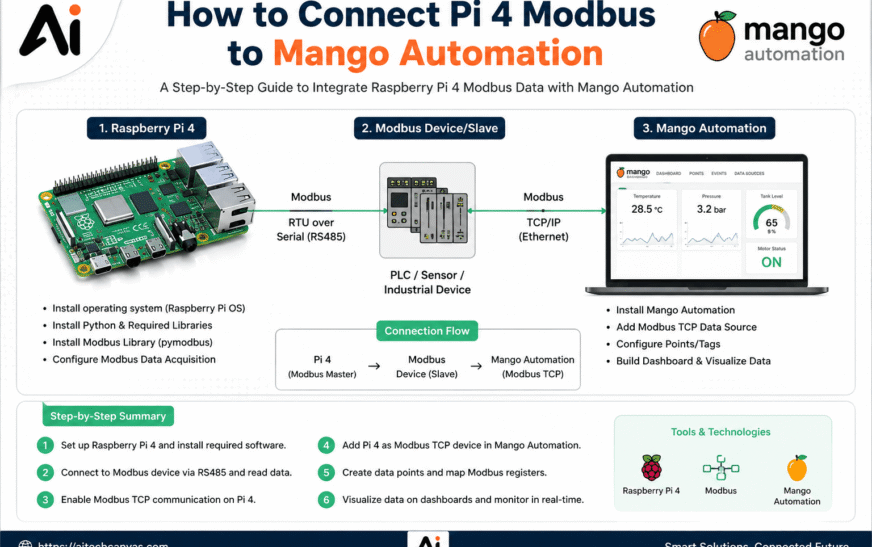
Industrial automation relies on standardized communication protocols to bridge physical edge hardware with supervisory control and data acquisition systems. Connecting a Raspberry Pi 4 to Mango Automation using the Modbus protocol turns a compact single-board computer into an enterprise-grade telemetry node.
This integration allows the Raspberry Pi 4 to collect localized sensor metrics, process edge data, and expose that information directly to Mango Automation for central visualization, logging, and alarming.
Understanding the operational structure of the protocol and selecting the correct interface method ensures a stable, low-latency telemetry link across your industrial network.
What Is Modbus and How Does It Work?
Industrial Automation relies on standardized communication protocols to share sensor readings, control signals, and device status between hardware systems. Modbus stands as one of the most widely deployed open-standard protocols in industrial automation and process control networks. Developed originally in 1979 by Modicon, this protocol uses a simple request-and-response messaging structure to transfer data across serial lines and Ethernet networks.
The core design of Modbus centers on organized numerical storage locations called registers and coils. A master device initiates queries, and a slave device processes those requests to return values or update internal outputs. Because the protocol header does not contain complex overhead, transmission speeds remain fast and predictable even across low-bandwidth connections.
Data within a Modbus device sits in four distinct memory tables. Each table handles a specific data type and access level:
- Discrete Inputs store single-bit read-only binary values representing digital inputs like switch states or proximity sensors.
- Coils store single-bit read-write binary values used to drive physical relay outputs or control flags.
- Input Registers hold 16-bit read-only numerical data gathered from analog instruments like temperature sensors and pressure transmitters.
- Holding Registers hold 16-bit read-write numerical values used for system configuration parameters, setpoints, and calculated outputs.
Every Modbus message contains an address field specifying the destination device, a function code identifying the requested action, data bytes containing payload or register addresses, and an error-checking calculation. When a server receives a frame, it evaluates the function code to verify whether to perform a read or write operation on the designated memory addresses.
Modbus TCP vs. Modbus RTU
Choosing between Modbus TCP and Modbus RTU depends heavily on physical network architecture, required cabling distance, and hardware interfaces. While both variants use identical application-level data structures and function codes, their physical layer transmission methods differ completely.
Modbus RTU uses serial transmission over RS-485 or RS-232 differential wiring. Data frames are encoded using compact binary characters, where each 8-bit byte is transmitted as two 4-bit hexadecimal characters. Message boundaries are determined by silent intervals on the transmission line equal to at least 3.5 character times.
Modbus TCP embeds standard Modbus application frames inside TCP/IP packets transmitted over standard Ethernet or Wi-Fi networks. Instead of using slave addresses embedded in the serial byte stream, network routing relies on standard IP addresses along with an explicit MBAP header attached to the payload.
Key differences between the two standards include:
- Transmission speed where Modbus TCP runs at standard Ethernet speeds of 100 Mbps to 1 Gbps, whereas Modbus RTU typically operates between 9600 bps and 115200 bps.
- Network topology where Modbus RTU uses a linear daisy-chain bus structure, while Modbus TCP utilizes flexible star topologies built on standard network switches.
- Distance constraints where serial RS-485 reaches up to 1200 meters without repeaters, while single Ethernet cable segments max out at 100 meters unless extended by network switches.
- Error detection mechanisms where Modbus RTU relies on a 16-bit CRC check, whereas Modbus TCP delegates integrity checks directly to the underlying TCP/IP stack.
Modbus Master and Slave Roles
Understanding protocol roles is essential when planning network routing and client-server relationships between hardware nodes. In traditional Modbus terminology, devices operate as either a Master or a Slave. In modern Ethernet context, these roles correspond directly to a Client and a Server.
A Modbus Master controls network traffic by issuing requests to remote devices. The master determines polling schedules, sends read commands to inspect remote registers, and sends write commands to update remote outputs. Standard Modbus networks allow only one primary master on a serial line at any given time to prevent packet collisions.
A Modbus Slave continuously listens for incoming requests matching its unique unit identifier. When a valid packet arrives, the slave reads or writes the requested internal registers and sends a structured response back to the requester. Slave nodes never initiate communication on their own.
In a Mango Automation and Raspberry Pi 4 architecture, the roles are clearly defined:
- Mango Automation operates primarily as the Modbus Master or client, initiating scheduled polling routines to retrieve real-time data points from remote hardware.
- Raspberry Pi 4 operates as a Modbus Slave or server, hosting sensor values, system health metrics, or relay states inside memory registers ready for collection.
How Raspberry Pi 4 Fits Into a Modbus Network
The Raspberry Pi 4 serves as a bridge between physical field devices and upper-level supervisory control and data acquisition systems. Featuring a quad-core ARM Cortex-A72 processor operating at 1.5 GHz, up to 8 GB of LPDDR4 RAM, and native Gigabit Ethernet, the single-board computer handles real-time industrial data routing effortlessly.
In an industrial deployment, the Raspberry Pi 4 collects low-level signals from digital sensors, I2C temperature modules, SPI analog-to-digital converters, or local GPIO pins. Software running on Raspberry Pi OS maps these raw sensor inputs directly into internal Modbus holding registers or input registers.
Once mapped, the Pi exposes those memory locations over its Gigabit Ethernet port using a light Modbus server daemon. Mango Automation connects across the local area network to query these exposed registers at specified intervals.
Alternatively, by adding an RS-485 HAT or a USB-to-RS485 transceiver to the hardware header, the Raspberry Pi 4 acts as a protocol converter. It can poll local serial sensors via Modbus RTU and re-publish those variables over Modbus TCP for centralized Mango Automation dashboards.
What You Need Before Connecting Pi 4 to Mango Automation
Establishing a rock-solid communication channel requires preparing hardware connections, network parameters, and software packages before writing configuration files. Preparing these foundational layers eliminates connectivity errors during initial testing.
Review these prerequisite components before proceeding with setup:
- A Raspberry Pi 4 running an updated version of Raspberry Pi OS with SSH enabled for remote terminal access.
- A reliable 5V 3A USB-C power supply to guarantee system stability under CPU load.
- A host machine or server running Mango Automation version 3.x or 4.x with the Modbus module installed.
- A wired Ethernet connection or static Wi-Fi connection joining both devices to the same network subnet.
- Hardware expansion adapters like a USB-to-RS485 FTDI adapter if using Modbus RTU instead of Ethernet.
Raspberry Pi 4 and Network Connection
Stable network configuration forms the foundation of reliable industrial telemetry. The Raspberry Pi 4 must maintain a fixed IP address so that Mango Automation can continuously open TCP sockets without losing connection due to dynamic lease changes.
Connecting the Pi using a direct CAT6 Ethernet cable to an industrial switch provides low latency and isolates the system from wireless interference. Static address assignments should be configured directly within /etc/dhcpcd.conf or through DHCP reservations inside your network router.
Modbus Software or Server on Raspberry Pi
The Raspberry Pi 4 does not run a Modbus server natively out of the box. You must install a lightweight open-source protocol library to host register memory in system RAM.
Python-based frameworks like pymodbus or pyModbusTCP provide simple scriptable environments to define custom registers and map system variables. Advanced deployments can also use compiled C libraries such as libmodbus or containerized node environments like Node-RED to manage server daemons.
Mango Automation Installation
Mango Automation operates as a Java-based SCADA platform designed for high-throughput time-series data collection. It runs on Linux, macOS, or Windows environments and hosts an intuitive web application interface.
Before configuring data points, ensure the Modbus IP and Modbus Serial core data source modules are active inside the Mango system administration panel. These modules enable native client drivers capable of polling remote Modbus endpoints.
Modbus Register Information
A clear register map must be established before setting up data points inside the supervisory platform. The register map defines where each data value resides, how many bytes it occupies, and how numbers should be parsed.
You need to record four primary attributes for every variable:
- Register Address specifying the numerical index from 0 to 65535.
- Register Type defining whether the variable resides in Holding, Input, Coil, or Discrete storage.
- Data Type denoting whether the register holds 16-bit unsigned integers, 32-bit floating-point numbers, or binary bits.
- Byte Order dictating Big-Endian or Little-Endian byte arrangement across multi-register values.
IP Address, Port, and Slave ID
Connecting two Modbus nodes across Ethernet requires three core identification metrics. Missing or incorrectly entering any of these parameters prevents the master from establishing a valid session.
- IP Address points directly to the Raspberry Pi 4 on the network, such as 192.168.1.50.
- Port Number defaults to 502 for standard Modbus TCP communication traffic.
- Slave ID or Unit Identifier defaults to 1 in single-device TCP links but routes messages to specific downstream devices when bridging to serial nodes.
Choose the Right Modbus Connection Method
Selecting between Modbus TCP and Modbus RTU dictates physical wiring choices, hardware expansion requirements, and system configuration steps. Evaluating your physical setup helps determine the optimal protocol variant.
Connecting Pi 4 to Mango Using Modbus TCP
Using Modbus TCP is the simplest and most robust setup method when both the Raspberry Pi 4 and the host running Mango Automation reside on the same Ethernet network. Data frames travel directly over IP sockets, removing the need for specialized serial converters.
This method supports high polling rates, allows multiple masters to read data concurrently if configured, and simplifies network troubleshooting using standard ping commands and packet capture tools.
Connecting Pi 4 to Mango Using Modbus RTU
Modbus RTU is necessary when the Raspberry Pi 4 connects to Mango Automation over long physical distances without existing network infrastructure or when integrating with legacy serial loops.
This approach requires an RS-485 transceiver connected to the Pi hardware UART pins or a USB-to-RS485 adapter. Matching baud rates, parity settings, and stop bits across all physical nodes is mandatory for reliable data frames.
When to Use Modbus TCP Instead of Serial
Modern industrial monitoring systems favor Modbus TCP for new installations due to superior bandwidth, simplified cable management, and seamless integration with existing network gear.
Consider using Modbus TCP whenever:
- Both devices reside within range of a shared local area network or VPN tunnel.
- Polling frequencies need to occur faster than 100 milliseconds per request cycle.
- Multiple software applications need access to telemetry generated by the Raspberry Pi 4.
- Installation budget demands avoiding dedicated RS-485 wiring runs and specialized serial gateways.
Configure Modbus on Raspberry Pi 4
Setting up a Raspberry Pi 4 as a Modbus server requires system updates, Python dependencies, and a stable network configuration. First, update the system and install the required Python tools, then create an isolated virtual environment for the Modbus application. This prevents dependency conflicts with system packages and allows you to install the required libraries safely.
For reliable Modbus TCP communication, configure the Raspberry Pi with a static IP address so its address does not change after a reboot. Add the following settings to /etc/dhcpcd.conf, restart the network service, and verify the assigned address with ip addr show eth0. Next, create modbus_server.py with a pymodbus datastore containing holding registers and start the TCP server on port 5020. Standard Modbus TCP uses port 502, but port 5020 is convenient during development because ports below 1024 generally require elevated Linux permissions.
Define Modbus Registers
Mapping registers correctly ensures physical parameters translate into standard numerical structures. Memory locations must follow standard Modbus data allocation boundaries.
The example script maps holding registers to real-world metric values:
- Holding Register 40001 (Offset 0): Ambient temperature scaled by 10 (e.g., 215 represents 21.5 °C).
- Holding Register 40002 (Offset 1): Relative humidity scaled by 10 (e.g., 480 represents 48.0%).
- Holding Register 40003 (Offset 2): Atmospheric pressure in hectopascals (e.g., 1013 hPa).
- Holding Register 40004 (Offset 3): Status flag (e.g., 0 for normal operational state, 1 for active system fault).
- Holding Register 40005 (Offset 4): System uptime timer counter value in minutes.
Configure the Modbus Slave ID
When working over Modbus TCP, individual network sockets use IP addressing for packet routing. The Slave ID (also called Unit ID) resides inside the MBAP header.
- For direct point-to-point Ethernet connections, set the Slave ID value to 1.
- If the Raspberry Pi operates as an intermediate RS-485 gateway, set unique Slave IDs ranging from 1 to 247 to differentiate downstream hardware devices connected to the same serial loop.
Start the Modbus Service
Test the Modbus Server
Testing the daemon interactively verifies that the Modbus server is working correctly before running it as a background service. Run python3 modbus_server.py in the Raspberry Pi terminal. If the server starts successfully, you can proceed with configuring it as a systemd service.
Create a systemd Service
To keep the Modbus daemon running reliably after reboots, create a service file at /etc/systemd/system/modbus.service. Add the required service configuration, including the Python environment path, the Modbus server script, and automatic restart settings.
Enable and Start the Modbus Service
After creating the service file, run sudo systemctl daemon-reload to reload the systemd configuration. Then use sudo systemctl enable modbus.service to configure the service to start automatically at boot, followed by sudo systemctl start modbus.service to start it immediately.
Check the Service Status
Finally, run sudo systemctl status modbus.service to verify that the Modbus service is active and running correctly. If the service is running successfully, the Raspberry Pi is ready to provide Modbus data to Mango Automation.
Configure Mango Automation for Modbus
Mango Automation retrieves device variables across network connections through its protocol driver engine.
Log into your Mango Automation browser dashboard (typically accessible at http://<your-mango-ip>:8080) using administrative credentials. Navigate to the main menu and select Administration, then click Data Sources.
Open the Modbus Data Source
Create a new communication channel inside the administration view:
- Locate the Data Source drop-down selector menu.
- Choose Modbus IP from the available driver list.
- Click the + (Add Data Source) button to open the parameters view.
- Set a clear name such as Raspberry Pi 4 Telemetry Gateway.
Enter the Raspberry Pi IP Address
Scroll to the primary connection properties section:
- Input the target Host Address matching the static IP assigned to the Raspberry Pi (192.168.1.50).
- Ensure the Transport Type parameter is set to TCP.
Configure the Modbus Port
Match the destination port configured in your Python daemon:
- Change the Port field from default 502 to 5020 if using non-privileged user ports on the Pi.
- Leave the setting at 502 if the server process on the Raspberry Pi was launched with root privileges.
Set the Polling Interval
The polling interval dictates how often Mango Automation issues read queries to update internal data points:
- Set Update Period to 2.
- Set time units to Seconds.
- Set Timeout to 1000 milliseconds to allow sufficient time for responses before throwing read exceptions.
- Set Retries count to 2 to handle temporary network packet loss gracefully.
Select the Appropriate Modbus Connection Type
Ensure the physical transport selection matches your environment:
- Choose TCP Keep-Alive if the socket connection should remain open continuously, reducing network traffic overhead.
- Choose TCP Master if Mango needs to open and close new connection sockets for every polling cycle.
Save the data source configuration by clicking the Save icon. Do not enable the data source until individual points are configured.
Add Raspberry Pi Modbus Data Points in Mango
Data points convert raw binary register values into readable engineering units inside Mango Automation.
Navigate to the bottom section of your newly created Modbus IP Data Source view and click Add Data Point.
Configure the Slave ID
Inside the point property configuration dialog:
- Enter 1 in the Slave ID field.
- Ensure this value matches the context configuration declared in your Pi Python daemon script.
Select the Modbus Register Type
Select the exact register block containing your parameter:
- Choose Holding Registers (Read/Write 4x memory block).
- Use Input Registers (3x memory block) if your Pi script is configured to expose read-only metrics.
Enter Register Addresses and Offsets
Address configurations can use either 0-based indexing (offsets) or 1-based indexing depending on display settings:
- For Holding Register 40001, set Offset to 0.
- For Holding Register 40002, set Offset to 1.
- For Holding Register 40003, set Offset to 2.
Set Data Types and Register Length
Assign matching data conversion types:
- Select 2-Byte Unsigned Integer for standard 16-bit numeric values.
- Select 4-Byte IEEE 754 Floating Point if your system encodes decimal values across two consecutive registers.
- For scaled integer fields (like 215 representing 21.5 °C), navigate to Value Modifiers, enable Multiplier, and set the scale factor value to 0.1.
Configure Read and Write Permissions
Set access boundaries for system operators:
- Check Settable if the variable represents a control output (such as a relay output or setpoint) that operators can modify from Mango dashboards.
- Leave Settable unchecked for read-only values like ambient sensor measurements.
Click Save on each configured data point. Finally, toggle the master Enable Data Source switch to start active network polling.
Test the Pi 4 and Mango Modbus Connection
Validating network connectivity step-by-step helps isolate issues before deploying dashboards.
1. Check Network Connectivity
Confirm network connectivity and routing between the Mango Automation host and the Raspberry Pi 4.
Open a terminal on the Mango Automation host and run a ping test against the Raspberry Pi 4 IP address:
ping 192.168.1.50 -c 4
Verify that the round-trip response time remains below 5 milliseconds and that there are zero dropped packets.
2. Test the Modbus Port
Verify that the Modbus daemon is listening and that the target port is accessible from the Mango Automation server.
3. Use the Mango Point Locator
Test Modbus queries directly from the Mango Automation interface.
- Open the Modbus Read Tool from the Mango Administration menu.
- Select the appropriate Modbus IP Network properties.
- Set the Slave ID to
1. - Select Holding Register as the register type.
- Click Read.
The tool should display the raw hexadecimal and decimal array values returned directly from the Raspberry Pi 4.
4. Verify Register Values
Confirm that Mango correctly parses the live Modbus register values. Navigate to Data Points / Watch List in Mango Automation and observe the live reading for Temperature Sensor 1.The temperature should display as:21.5 °C. This value is obtained after applying the 0.1 multiplier factor to the raw register value.
5. Monitor Modbus Communication Logs
Analyze the real-time Modbus communication frames on the Raspberry Pi 4. Verify that the logs show active read operations and incoming polling requests from Mango Automation. Valid transactions should complete without:
- Index-out-of-bounds errors
- Socket disconnect warnings
- Connection failures
- Modbus communication errors
Successful logging confirms that Mango Automation is communicating correctly with the Raspberry Pi 4 Modbus daemon.
Troubleshoot Common Pi 4 Modbus Connection Problems
Network issues, permission errors, and data format mismatches can cause communication failures. Below are common causes and solutions.
Mango Cannot Reach the Raspberry Pi
- Cause: Incorrect IP settings, disconnected Ethernet cables, or isolated subnets.
- Solution: Verify physical link LEDs on the Pi network port. Ensure both devices share the same gateway and subnet mask settings (255.255.255.0).
Connection Timeout Errors
- Cause: The Modbus daemon is stopped, listening on a different port, or blocked by a firewall.
- Solution: Check system daemon status on the Pi using systemctl status modbus.service. Confirm the script is configured to listen on 0.0.0.0 (all interfaces) rather than 127.0.0.1 (localhost only).
No Response From Slave
- Cause: Mismatched Slave ID or wrong connection protocol type selected inside Mango.
- Solution: Verify that the Slave ID setting inside the Mango data point details matches the context slave value declared in the Python script.
Incorrect Register Addresses
- Cause: Off-by-one errors caused by mixing 0-based and 1-based register indexing styles.
- Solution: If requesting register 40001 returns the value for 40002, subtract 1 from the offset field inside Mango’s point configuration.
Wrong Slave ID
- Cause: Point request headers specify an unconfigured unit ID.
- Solution: Ensure all data points added under a single Modbus IP data source use matching Slave ID numbers unless polling distinct downstream devices through a serial gateway.
Incorrect Data Type or Byte Order
- Cause: Multi-register data values like 32-bit floats display distorted or unexpected numbers.
- Solution: Adjust the byte swap and word swap toggles inside Mango’s point settings (e.g., change from Big-Endian to Little-Endian with Byte Swap).
Modbus Port or Firewall Problems
- Cause: Linux iptables or ufw firewalls blocking incoming socket connection requests on port 502 or 5020.
- Solution: Allow Modbus TCP port traffic through the Pi firewall using:
Bash
sudo ufw allow 5020/tcp
Monitor Raspberry Pi Modbus Data in Mango
Once connection parameters are confirmed, set up logging schedules, real-time visual dashboards, and automated alert limits.
Create Data Points for Live Values
Map all remaining holding registers created in your Python daemon:
| Point Name | Register Type | Offset | Modbus Data Type | Scale Factor | Unit |
| Ambient Temperature | Holding Register | 0 | 2-Byte Unsigned Integer | 0.1 | °C |
| Relative Humidity | Holding Register | 1 | 2-Byte Unsigned Integer | 0.1 | % |
| Barometric Pressure | Holding Register | 2 | 2-Byte Unsigned Integer | 1.0 | hPa |
| System Fault Status | Holding Register | 3 | 2-Byte Unsigned Integer | 1.0 | Binary |
| Gateway Uptime | Holding Register | 4 | 2-Byte Unsigned Integer | 1.0 | Minutes |
Display Modbus Data on Mango Dashboards
Build clear dashboard interfaces using Mango’s graphical editor:
- Open Administration and navigate to UI Dashboards.
- Add a new view layout and insert Gauge and Text Display components.
- Bind the Gauge Component directly to the Ambient Temperature point.
- Set gauge upper and lower limits (-10 °C to 50 °C).
- Bind digital status variables to state indicator icons to show green for normal operation or red for system fault conditions.
Configure Historical Data Storage
Historical trends help track operational performance over time:
- Open individual Data Point Settings inside Mango.
- Locate the Logging Properties configuration tab.
- Set Logging Type to All Changes for discrete state variables.
- Set Logging Type to Interval for continuous values like temperature, setting the logging frequency to every 10 seconds.
Set Up Alarms and Events
Automated alarm triggers notify operators when metrics cross critical thresholds:
- Navigate to Event Detectors within the target data point edit view.
- Click Add Event Detector and select High Limit.
- Set the trigger value limit to 35.0 °C and assign an alarm level of High.
- Link an Email Handler action to send automatic notifications to maintenance teams when elevated temperature events occur.
Best Practices for Pi 4 and Mango Modbus Integration
Following industrial integration standards ensures reliable performance and reduces downtime.
Use Stable IP Addresses
Never rely on dynamic leases for core telemetry links. Always assign fixed static IP addresses at the operating system level or create permanent MAC address reservations inside your network router.
Match Modbus Communication Settings
Double-check that all network parameters—including IP address, port number, slave ID, register index offsets, and data decoding models—match across both the Raspberry Pi daemon and Mango Automation configurations.
Document the Register Map
Maintain a central register documentation sheet tracking register addresses, variable names, scaling multipliers, variable data types, and engineering units. Keep this reference updated whenever new points are added.
Choose an Appropriate Polling Rate
Avoid setting polling intervals unnecessarily fast. Polling every 1 to 2 seconds is sufficient for environmental telemetry. Rapid polling below 100 milliseconds can cause network congestion and unnecessary CPU usage on the Pi.
Secure the Modbus Network
Standard Modbus TCP lacks native encryption or authentication mechanisms. Protect industrial installations by isolating traffic on a dedicated VLAN, enforcing strict firewall rules, or routing traffic through secure WireGuard or OpenVPN tunnels when traversing external networks.
Connecting a Raspberry Pi 4 to Mango Automation through Modbus provides a practical way to collect, monitor, and manage industrial sensor data from a centralized platform. The Raspberry Pi can act as a Modbus server or gateway, while Mango Automation polls the available registers and presents the data through dashboards, historical logging, and alarms.
For a reliable integration, it is important to use stable network settings, match the IP address, port, Slave ID, register addresses, and data types on both systems, and maintain a clear register map. Security should also be considered because Modbus TCP does not provide built-in encryption or authentication.
Overall, the Raspberry Pi 4 and Mango Automation combination offers a flexible and cost-effective approach for industrial telemetry, allowing real-time monitoring, historical data analysis, and automated alerts while supporting both Modbus TCP and Modbus RTU configurations.
Conclusion
Connecting a Raspberry Pi 4 to Mango Automation through Modbus provides a practical way to collect, monitor, and manage industrial sensor data from a centralized platform. The Raspberry Pi can act as a Modbus server or gateway, while Mango Automation polls the available registers and presents the data through dashboards, historical logging, and alarms.
For a reliable integration, it is important to use stable network settings, match the IP address, port, Slave ID, register addresses, and data types on both systems, and maintain a clear register map. Security should also be considered because Modbus TCP does not provide built-in encryption or authentication.
Overall, the Raspberry Pi 4 and Mango Automation combination offers a flexible and cost-effective approach for industrial telemetry, allowing real-time monitoring, historical data analysis, and automated alerts while supporting both Modbus TCP and Modbus RTU configurations.
FAQs
Can Raspberry Pi 4 Run a Modbus Server?
Yes, the Raspberry Pi 4 can run lightweight Modbus TCP and RTU servers using open-source libraries like pymodbus, pyModbusTCP, or libmodbus.
Can Mango Automation Connect to Raspberry Pi Using Modbus TCP?
Yes, Mango Automation includes a native Modbus IP driver that connects directly to a Raspberry Pi running a Modbus TCP server daemon over standard Ethernet or Wi-Fi networks.
What Port Does Modbus TCP Use?
Standard Modbus TCP uses Port 502. Non-root applications on Linux often use custom ports like 5020 to avoid requiring elevated privileges.
How Do I Find the Raspberry Pi Modbus Register Address?
Register addresses are defined inside the code or service running on the Raspberry Pi. Refer to your server script or device documentation to locate the exact register index offsets and memory structures.
Why Does Mango Show No Response From Slave?
This error typically occurs due to incorrect IP addresses, mismatched port settings, wrong Slave IDs, or firewall rules blocking network traffic on the Pi.
Can Raspberry Pi 4 Use Modbus RTU With Mango?
Yes, adding a USB-to-RS485 adapter or an RS-485 HAT allows the Raspberry Pi 4 to communicate with Mango Automation via Modbus RTU over serial links.